Interact with the Work Instructions tab and panels
The Work Instructions tab shows process content relevant to one worker in one shift. It does not display or navigate an entire process plan.
If you have not done so already, open an existing work package, or create a package and browse to the process for which you want to author instructions.
Click the Work Instructions tab.
By default, the screen opens processes in the Overview panel in a collapsed state and no parts or resources are visible in the Viewer panel.
To visualize parts and resources:
For all processes and operations in the Overview panel, click the root node.
For specific processes and operations in the Overview panel, including consumed parts and assigned resources, select the
 check box next to each line in the Overview panel and assigned data (consumed parts and assigned resources).
Selected processes and operations now visible in the Viewer panel display a checkmark.
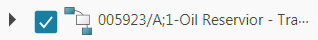
Parts and resources assigned to the selected processes and operations are displayed in the Viewer panel.
 Tip:
Tip:Displaying additional data in the graphic viewer may cause the viewer to zoom out. Click to refresh the view.
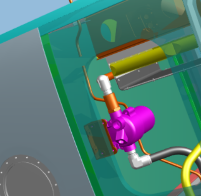
Drag the 3D model to rotate and inspect it in the Viewer panel; use your mouse wheel to zoom in and out, and press your middle and right mouse buttons to pan.
 Note:
Note:If you do not have a middle mouse button, press your scroll button and right button to pan.
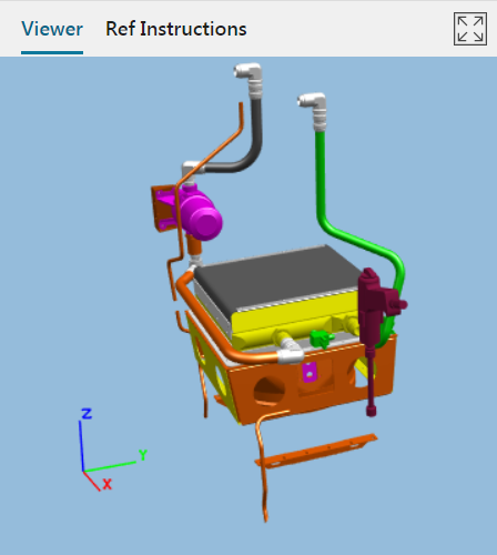
To add product information, an object note, or a free note to a part in the Viewer, select the part, click , and do one of the following:
To display part number, revision, and part name, click Add Object Information.
The Viewer displays object information attached to the selected part.
To create a object note containing general information about a part or resource, click Add Object Note. In the Create Note dialog box, type the required information, and then click Done.
To create a free-style note, click Add free note, and in the Create Note dialog box, type the required information, and then click Done.
Note:You can also add a symbol to a free-style note, or use the Preset list to add text styles to a selected line in the note.
You must define the styling presets with the WI_SavedPresets preference before you can use preset styles. See Configuring Work Instructions Authoring in the EasyPlan 2.11 Deployment for information about defining this preference.
Note:You can also add a symbol to a free-style note, or use the Preset list to add text styles to a selected line in the note.
(Optional) Change the font, font size, and text color in the Create Note dialog box.
Note:As needed, select the text and use text styles to emphasize a certain situation to workers on the shop floor, such as a red color to indicate a hazardous or dangerous step, or a gray color to indicate reference geometry.
If you receive a dialog stating that the operation needs to revised because of a revision change, click Yes, Revise or Cancel.
You can remove a label or note at any time by selecting the object and clicking Delete object information .
To edit text after it has been created, in the Viewer, double-click the note.
To change the color and transparency of a part in the Viewer, select the part and click Highlight Part .
In the Highlight Part dialog box, select a color. To change the transparency of the part so that you can see parts behind it, drag the Set Transparency slider to the appropriate percentage.
Click Apply.
To remove transparency and return to the original color, select the part, open the Highlight Part dialog box again, and click Reset.
To see the color and transparency, deselect the part by clicking outside the assembly.