Using topology optimization
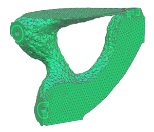
In this tutorial, you will create a bracket using topology optimization. The software minimizes the compliance of the bracket while using only 10–30% of the original weight and constraining the frequency of mode 7 to one third of its original value.
-
On your desktop or the appropriate network drive, create a folder named topology_optimization.
-
Click the link below:
Note:The part files require about 1.4 GB of free disk space and might take some time to download.
-
Extract the files to your topology_optimization folder.
-
Start Simcenter 3D or NX.
-
Open Bracket 02_sim1.sim.
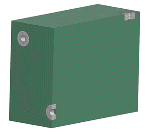
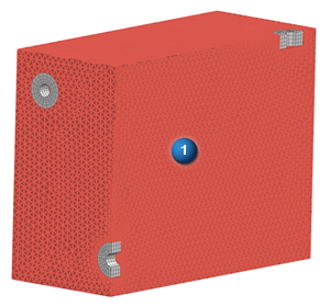
This model represents a bracket that will be affixed to two surfaces with four screws. Since the bracket is intended to be symmetrical, you will optimize only half of the model to reduce processing time.
The options you select in dialog boxes are preserved for the next time you open the same dialog box within a given session. Restore the default settings to ensure that the dialog boxes are in the expected initial state for each step of the activity.
|
File |
Preferences→User Interface
-
Options
-
 Reset Dialog Memory
 -
OK
You want the bracket to be as stiff as possible while reducing its weight and constraining one of its modes to not go below a specified frequency. To determine the constraints to impose, you must examine the model's existing weight and the frequency of its modes. A solved Simcenter Nastran SOL 103 Real Eigenvalues solution is provided to enable you to view the frequencies.
 Solid Properties Check (Home tab→Checks and Information group→More list)
-
 Drag a selection box around the entire model
-
OK
The Information window indicates that the total mass is about 9.6E-03 lbf-s2/in.
-
 the Information window
![]() Simulation Navigator
Simulation Navigator
-

 Test Normal Modes→Results
 -
 Structural
![]() Post Processing Navigator
Post Processing Navigator
-
Test Normal Modes→Structural
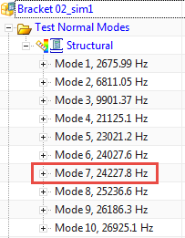
Observe the frequencies of each mode. Mode 7 has a frequency of about 24228 Hz.
For this solution, you will specify 35 design cycles, and indicate that a linear relationship exists between the material density and the Young's Modulus.
![]() Simulation Navigator
Simulation Navigator
-
Bracket 02_sim1.sim
-
 New Solution
 -
Name
TO Statics and Modes
-
Solution Type
SOL 200 Topology Optimization

-
Bulk Data
-
Maximum Number of Design Cycles (DESMAX)
35
-
Penalty Law (DMRLAW)
Linear
-
 Create Modeling Object (Parameters)
-
AUTOMPC
YES
-
OK
all dialog boxes
The frequency design constraint should be applied to a normal modes subcase.
![]() Simulation Navigator
Simulation Navigator
-
TO Statics and Modes
-
New Subcase
-
Step
Nastopt - Normal Modes
-
OK
![]() Simulation Navigator
Simulation Navigator
-
Constraint Container
-
Fixed
-
Ctrl
+
Symmetric
-
TO Statics and Modes→Nastopt - Statics1→Constraints
Repeat this procedure to add the constraints to the Nastopt - Normal Modes 1 subcase as well.
-
Load Container
-
Force(1)
-
TO Statics and Modes→Nastopt - Statics1→Loads
The design objective is to minimize compliance in the structure (that is, maximize stiffness). This procedure creates a design objective modeling object and a design response quantities modeling object simultaneously, and adds the design objective to the statics subcase. Objectives that are specific to a subcase should appear at the subcase level.
![]() Simulation Navigator
Simulation Navigator
-
TO Statics and Modes→Nastopt - Statics 1
-
Design Objective
-
New or Replace Design Objective
-
Name
Minimize Compliance
-
Response Type
Compliance (CMPLNCE)
-
Optimization Method
MIN
-
OK
To ensure that elements are not removed near the screw holes, the model includes a mesh around each hole, and a separate mesh for the rest of the solid body. You will limit the design area to the mesh for the rest of the body.
![]() Simulation Navigator
Simulation Navigator
-
TO Statics and Modes
-
Design Area
-
New Design Area
-
Name
Optimization Area
-
Area Type
Optimization Area
-
Label
DA1
-
Element Selection Method
Specified Elements
-
Type Filter (Top Border bar)
Mesh
-

-
OK
Without a weight constraint, the software would use as much material as possible to fulfill the objective of minimizing compliance. You can define weight constraints only at the solution level. In this case, you want the optimized part to weigh between 10–30% of the original weight, which you previously determined to be about 9.6E-03 lbf-s2/in.
![]() Simulation Navigator
Simulation Navigator
-
TO Statics and Modes
-
Design Constraint
-
New Design Constraint
-
Name
Weight Constraint
-
Response Type
Total Model Weight (WEIGHT)
-
Lower
0.001 lbf-s2/in
-
Upper
0.003 lbf-s2/in
Note:Be sure to change the unit of measurement to lbf-s2/in.
-
OK
As the optimization process removes material, the structure becomes more flexible. You will set the lower boundary for the frequency of mode 7 to 8000 Hz.
![]() Simulation Navigator
Simulation Navigator
-
TO Statics and Modes→Nastopt - Normal Modes 1
-
Design Constraint
-
New Design Constraint
-
Name
Frequency Constraint
-
Response Type
Normal Modes (FREQ)
-
Normal Modes Mode Number
7
-
Lower
8000
-
OK
Since this model takes a long time to solve, you can use the provided results with your solution.
![]() Simulation Navigator
Simulation Navigator
-
TO Statics and Modes→Results
-
Structural
-
Specify
-
 Browse (Results File Name)
-
Files of type
Nastran Results Files (*.op2)
-
File name
bracket_02_sim1-to_statics_and_modes.op2
-
OK
all dialog boxes
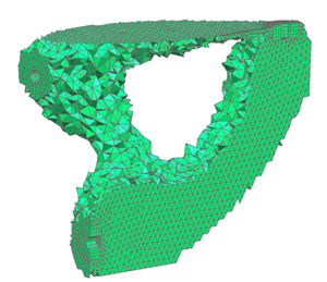
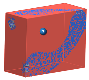
You will adjust the results of the final design cycle to show only the elements with a material density value of 0.7 or higher. You will also smooth the results and export the model as a faceted STL file.
![]() Simulation Navigator
Simulation Navigator
-
TO Statics and Modes→Results
-
 Structural
![]() Post Processing Navigator
Post Processing Navigator
-
TO Statics and Modes
-
Structural
-
Material Density Results
Result is automatically set to Design Cycle 35, which is the last design cycle.
-
Lower Bound
0.7
Tab
-
 Smooth (Nodal Average)
 -
Facets in STL Format
-
 Facets in Nastran BDF Format
 -
Export
-
the Information window
-
Close
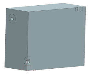
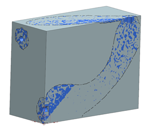
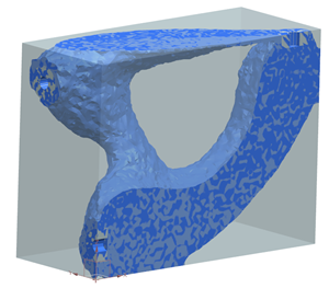
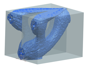
Importing the STL file into the original part file can help you visualize the optimized part in the Modeling application. You can also mirror the display to see the entire part.
![]() Simulation Navigator
Simulation Navigator
-
Bracket 02_sim1.sim→Bracket 02_fem1.fem
-
Bracket 02.prt
-
Load
-
Bracket 02.prt
-
Make Displayed Part
|
File |
-
All Applications→Modeling
|
File |
-
Import→STL
-
Browse (STL File)
-
Files of type
Stereo Lithography Files (*.stl)
-
File name
bracket_02_sim1-to_statics_and_modes.stl
-
OK
Part File dialog box
-
Facet Body Output Type
JT
-
STL File Units
Inches
-
OK
-
Rendering Style Drop-down (Top Border bar)
Shaded
|
View |
 Edit Object Display (Visualization group)
-
-
OK
Class Selection dialog box
-
Translucency

Drag to 50.
-
OK
Edit Object Display dialog box
|
|
-
View→Operation→Mirror Display
|
File |
-
Close→All Parts