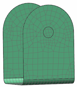
Creating a 2D mesh
In this tutorial, you will create a 2D mesh of a bracket.

-
On your desktop or the appropriate network drive, create a folder named twod_meshing.
-
Click the link below:
-
Extract the part file to your twod_meshing folder.
-
Start Simcenter 3D or NX.
-
Open bracket2.prt.

The options you select in dialog boxes are preserved for the next time you open the same dialog box within a given session. Restore the default settings to ensure that the dialog boxes are in the expected initial state for each step of the activity.
|
File |
Preferences→User Interface
-
Options
-
 Reset Dialog Memory
 -
OK
![]() Simulation Navigator
Simulation Navigator
-
 bracket2.prt
 -
 New FEM and Simulation
 -
 Create Idealized Part
 -
Solver
Simcenter Nastran

-
Analysis Type
Structural

-
OK
all dialog boxes
![]() Simulation Navigator
Simulation Navigator
-
Simulation File View
-
 bracket2_fem1_i
 -
 Make Displayed Part
 -
OK
Idealized Part Warning message box
Before you can modify the idealized part, you must place an associative copy of the master part file in the idealized part file. To do this, you can use the Promote command.
![]() Promote (Home tab→Start group)
Promote (Home tab→Start group)
-
 the bracket body
-
OK
Midsurface models are commonly used to simplify the analysis of thin-walled parts.
![]() Midsurface by Face Pairs (Geometry Preparation group)
Midsurface by Face Pairs (Geometry Preparation group)
-
 the bracket body
-
 Automatically Create Face Pairs
-
OK
Midsurface by Face Pairs uses the average thickness of all faces in the pair. The thickness near the blend areas may contribute more.
Because you will generate the mesh on the midsurface and not on the original part, you will now hide the original polygon body.
![]() Simulation Navigator
Simulation Navigator
-
Simulation File View
-
 bracket2_fem1
 -
 Make Displayed Part
 -
 the Information window
![]() Simulation Navigator
Simulation Navigator
-

 Polygon Geometry
 -

 Polygon Body (1) (hide)

Create the mesh collector that will define the associated physical property table and material for the mesh.
![]() Mesh Collector (Properties group)
Mesh Collector (Properties group)
-
Element Family
2D

-
Collector Type
Thin Shell

-
Name
Bracket
-
 Create Physical (Shell Property)
 -
Name
Bracket
-
 Choose material (Material 1)
 -
Materials
Steel

-
OK
Material List dialog box
-
Default Thickness
10 mm
-
OK
all dialog boxes
![]() 2D Mesh (Mesh group)
2D Mesh (Mesh group)
-
 Drag a box around the midsurface.
-
Type
CQUAD4

-
Element Size
10 mm
-
Destination Collector
-
 Automatic Creation
 -
Mesh Collector
Bracket

-
Note:
Make sure that you clear the Automatic Creation
 check box and select the mesh collector that you created in the previous step.
-
Apply
Apply generates the new mesh and keeps the 2D Mesh dialog box active.
-
OK
message box
-

-
Now refine the mesh in the fillets slightly by changing to a parabolic thin shell element and experimenting with the element size.
-
 the mesh
-
Type
CQUAD8

-
Apply
to remesh the part

-
The elements conform much better to the fillet radius and the hole outlines.
-
Cancel
2D Mesh dialog box
![]() Save
Save
|
File |
-
Close→All Parts