Data structure
Next Generation Planning data is organized in three layers based on role and level of detail.
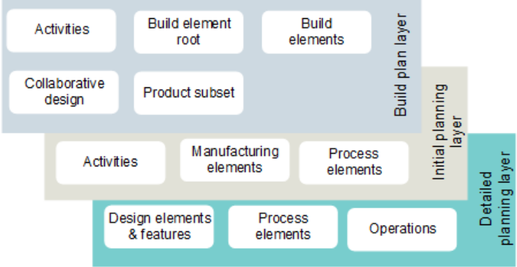
Next Generation Planning uses a twin structure that contains both manufacturing BOM (MBOM) and bill of process (BOP) information.
Build plan layer — At the highest level of the structure, the MBOM and BOP are identical. Activities are shared between the build play layer and the initial planning layer.
Initial planning layer — At this level the benefits of the twin structure occurs. For example, if you create, move, or delete an MBOM object, the same action is applied to the MBOM's twin BOP object. Process elements are shared between the initial planning layer and the detailed planning layer.
Detailed planning layer — At the lowest level of the MBOM structure, you find the design components and design features. At the lowest level of the BOP structure, you find the sequence of operations.
The twin MBOM/BOP structures follow this hierarchy of objects:
Build element root
The top level (root) object for Next Generation Planning. There is one build element root per unit (for example, vessel). Only an administrator can create a build element root.
Collaborative design
Collaborative designs are a 4GD container for all the design data in a product or program. There is one collaborative design per build element root. Only an administrator can associate a collaborative design to a build element root.
Build element
Build elements contain activities and other build elements that represents a logical portion of a build strategy, a method of dividing portions of a product (build elements and activities) into logical subsets for manufacture. Multiple levels of build elements can be used to represent the build plan, known as the ship breakdown structure in the ship building industry. On average you may have 250 build elements in a build element root.
Activity
Activities are located in a build element. An activity is a measurable amount of work (for example, assembling all or part of a rudder) associated with a collection of manufacturing and process elements and their related work units. An activity describes the high-level work performed to manufacturer the product. On average, you may have 50 activities per build element.
Note:This is a different object type than the activity object found in Teamcenter Manufacturing Process Planner.
Product subset
Product subsets are used in 4GD to group design components for a specific purpose. This defines the scope of work for an activity.
Manufacturing element
Manufacturing elements are located in an activity. On average you may have 100 manufacturing elements per activity. In the MBOM specific view of the structure, the manufacturing elements contain the associated design components and design features.
Process element
Process elements are located in an activity. On average you may have 100 process elements per activity. In the BOP specific view of the structure, the process elements contain the sequence of operations performed in the activity. For example, it contains the sequence of operations to weld two parts together.
Design component
Design components are located in a product subset. It is the 4GD equivalent of a part. For example, a design component could be piece of the rudder.
Design feature
Design features are located in a product subset. It is the 4GD equivalent of a weld.
Operation
Operations are located in a process element. You may have between 0 and 100 operations per process element, because not every process element is fully detailed. This is a low-level operation to perform a specific task. For example, an operation could tell the operator to pick up a part.